
38 posts found, showing 10 per page
Dealing with the coal seam.
Slide WVSORO May 5, 2022
Coal seams also need to be isolated from any gas pressure or invasion. For one thing, coal seams have a form of cracks called cleats that can allow the gas to travel broadly in the horizontal plane and cause problems anywhere the coal seam is breached or even if it comes to the surface Also, increasing the methane in coal seams makes them harder to mine. And finally, and most importantly, it would be very dangerous to miners for a continuous mining machine to cut through a gas well that was not properly plugged and leak poisonous and explosive gas into the coal mine! More
Using clay and cement to plug un-cemented, now un-cased, bore hole.
Slide WVSORO May 5, 2022
A special form of clay or other material is used for the next layer of plugging the borehole. This clay is often bentonite clay, a clay that expands as it soaks up water. It is very similar to kitty litter. It has other additives sometimes to do the best job. Probably because it is cheaper than cementing all the way to the top, most of the vertical height of the plug in the borehole is clay as we shall see in the next slides. It is shown as yellow in these slides. More
Killing the production formation and cementing above it.
Slide WVSORO May 5, 2022
After the tubing and un-cemented casing has been pulled out of the well, the plugger starts to actually plug up the bore hole headnidg up to teh surface plus any casing that is cemented into the bore hole. More
Slide WVSORO May 5, 2022
After the tubing and un-cemented casing has been pulled out of the well, the plugger starts to actually plug up the bore hole headnidg up to teh surface plus any casing that is cemented into the bore hole. More
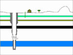
UN-cemented casing has been pulled.
Slide WVSORO May 5, 2022
This graphic shows that the casing pipe that is not cemented into the well borehole has been cut at the bottom and pulled out the same way the tubing was. The casing pipe that has been cemented into the borehole cannot be removed (except sometimes later for coal mining -- see later slide). It is hoped that the cementing of the cemented casing pipe that is left in at the time of plugging was done right when the well was drilled and cemented. More
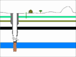
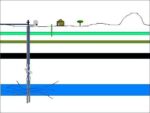
Tubing has been pulled and surface facilities removed.
Slide WVSORO May 5, 2022
This drawing shows that the tubing, shown as blue on previous slides, has been pulled out of the well and placed on the flatbed truck in the earlier picture, and the tank and wellhead and other equipment at the surface have been removed. More
Slide WVSORO May 5, 2022
This drawing shows that the tubing, shown as blue on previous slides, has been pulled out of the well and placed on the flatbed truck in the earlier picture, and the tank and wellhead and other equipment at the surface have been removed. More
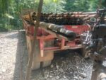
Tubing that has been pulled from well.
Slide WVSORO May 5, 2022
The plugging has begun. The pressure from the gas-bearing formation (and there is probably not much pressure left) has been "killed" as explained in a futuer slide. The plugger has started pulling out the tubing and loading it onto this flatbed truck to be hauled away and scrapped. The UN-cemented casing will also be pulled from the well and will be placed on this or a similar flat bed trailer and hauled away. More
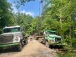
Some of the plugging equipment.
Slide WVSORO May 5, 2022
In this picture the time has come to plug the well and, as pictured here, some of the equipment that is needed to plug a well is brought to the site. Facing the camera on the right is a truck pulling a flat bed trailer on which the tubing and casing will be placed and hauled away once it is cut off at the bottom and pulled up out of the well. On the left facing the camera is a tank truck probably carrying water necessary to mix with the clay that is talked about later. More
Surface facilities.
Slide WVSORO May 5, 2022
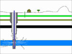
This drawing is simpler and a little more to scale, plus it also shows some of the larger surface features of an active gas well. These surface features/equipment include: The well head and its ipes connected on the top of the casing and tubing. A tank for oil at an oil well or at a gas well sometimes for brine or other liquids that sometimes comes up with the gas from some formations/locations. Some kind of metering/measuring system. More
Slide WVSORO May 5, 2022
This drawing is simpler and a little more to scale, plus it also shows some of the larger surface features of an active gas well. These surface features/equipment include: The well head and its ipes connected on the top of the casing and tubing. A tank for oil at an oil well or at a gas well sometimes for brine or other liquids that sometimes comes up with the gas from some formations/locations. Some kind of metering/measuring system. More
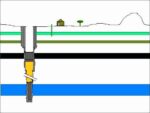
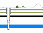
Tubing inside casing.
Slide WVSORO May 4, 2022
In addition to the metal casing pipe, another smaller metal pipe is inserted down to the producing target formation inside the smallest casing pipe. It shows up in blue in this drawing. This smaller pipe is called the "tubing". It is through this tubing pipe that the gas actually flows up to the surface. More
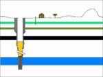
Properly drilled, cased, and cemented well before plugging.
Slide WVSORO May 4, 2022
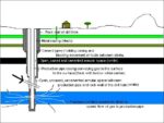
This slide shows a drawing of an oil or gas well after it has been properly drilled and cased/cemented. Several concentric layers of metal casing pipe have been inserted into the well borehole. Usually in West Virginia there is a surface casing pipe, and then inside that a casing pipe down through the coal and then inside that a “production” casing pipe all the way down into the target formation. More
Slide WVSORO May 4, 2022
This slide shows a drawing of an oil or gas well after it has been properly drilled and cased/cemented. Several concentric layers of metal casing pipe have been inserted into the well borehole. Usually in West Virginia there is a surface casing pipe, and then inside that a casing pipe down through the coal and then inside that a “production” casing pipe all the way down into the target formation. More